- Have any questions?
- +61 424 178 561
- +61 3 9837 5203
- [email protected]
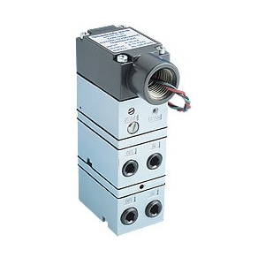
Explosion-Proof I/P Transducer
The Type-595XP Explosion proof I/P (current to pressure) transducer converts a 4–20mA electrical current signal to a proportionally linear pneumatic output. The unique conversion technology utilising open loop control, provides a high level of accuracy and repeatability for the operation of actuated valves. A low mass control circuit provides consistent output in high vibration applications.
The Type-595XP Explosion proof I/P (current to pressure) transducer converts a 4–20mA electrical current signal to a proportionally linear pneumatic output. The unique conversion technology utilising open loop control provides a high level of accuracy and repeatability for the operation of actuated valves. A low mass control circuit provides consistent output in high vibration applications.
This compact unit is housed in an explosion proof enclosure that is designed for pipe, bracket or direct manifold mounting. This explosion-proof and intrinsically safe field device is available with an integral volume booster or as a low-flow signal converter that directly mounts to a pneumatic valve positioner.
Multiple choices for wiring and porting simplify the installation and reduce the time required to do so. In addition to standard wall, panel or pipe mounting, optional DIN rail and manifold mounting kits are also available. The Type-925 Multifunction manifold provides a common supply port and individual shutoff valves for sets of 3, 5, 10 or 15 units.
Specifications
Functional Specifications
Performance Specifications Physical Specifications
| P Connection (with Flow Booster) | M & N Connection (without Flow Booster) | |||||||||||||
| Inputs |
|
|
||||||||||||
| Outputs |
|
|
||||||||||||
| Air Consumption | 0.1 scfm (0.17m3/hr) | 2.00 scfh (0.06 m3/hr) @ 20 psig supply (1.4 BAR)4.94 scfh (0.14 m3/hr) @ 85 psig supply (6.0 BAR)8.36 scfh (0.24 m3/hr) @150 psig supply (10.0 BAR) |
||||||||||||
| Supply Pressure Note: Supply pressure must be a minimum of 5 psig (0.3 BAR) above maximum output |
|
|
||||||||||||
| Flow Capacity | 2.4 scfm (4.1 m3/hr)max. | Same as Air Consumption | ||||||||||||
| Temperature Limits | -40°F to 158°F (-40°C to 70°C)
Low Temp (L) Option: -67°F to 158°F (-55°C to 70°C) |
-40°F to 158°F (-40°C to 70°C)
Low Temp (L) Option: -67°F to 158°F (-55°C to 70°C) |
||||||||||||
| Relative Humidity | 75% average – 95% short time non-condensing | 75% average – 95% short time non-condensing | ||||||||||||
| Impedance | 260 Ohms @ 70°F | 260 Ohms @ 70°F | ||||||||||||
| Loop Load | 5.2 Volts @ 70°F | 5.2 Volts @ 70°F |
Performance Specifications
| Linearity (Independent) | <± 0.5% of span | |
| Hysteresis | <±0.3% of span | |
| Deadband | <±0.1% of span | |
| Repeatability | <±0.3% of span; ±0.15% of span typical | |
| Mounting Orientation Effect | <±0.5% / 90 degree change | |
| Air Supply Sensitivity | <.3% / 1.5 (0.10 BAR) psig change | <±0.6% / 25 (1.72 BAR) psig change |
| Vibration Effect | <±1% up to 10g and 20-80 Hz |
|
| Temperature Effect | <±0.75% / 10°F (5.6°C) change | |
Physical Specifications
| Housing | NEMA 4X (IP 65) | ||||
| Port Sizes |
|
||||
| Media | Clean, dry, oil-free, instrument air, filtered to 40 micron | ||||
| Electrical Connections | Terminal block | ||||
| Mounting | Direct (standard) or 2″ pipe (optional) | ||||
| Mounting
|
Housing: Chromate-treated aluminum with epoxy paint. NEMA 4X (IP65)
Elastomers: Buna-N Trim: Stainless steel; brass; zinc-plated steel |
||||
| Weight | P version=1.40 lbs (0.64 kg) N version=1.25 lbs (0.57 kg) M version=1.20 lbs (0.54 kg) |
Applications
A low mass control circuit in compact housed unit provides consistent output in high vibration applications and is used in hazardous areas.