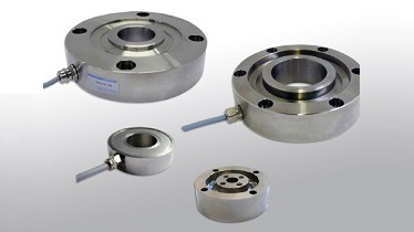
Force Sensors & Load Cells
Strain gauge load cells are the most common in industry. Strain gauge load cells work on the principle that the strain gauge deforms when the material of the load cells deforms appropriately. Deformation of the strain gauge changes its electrical resistance, by an amount that is proportional to the strain. The change in resistance of the strain gauge provides an electrical value change that is calibrated to the load placed on the load cell. These load cells are particularly stiff, have very good resonance values, and tend to have long life cycles in application.
 Operating Principle
The gauges themselves are bonded onto a beam or structural member that deforms when weight is applied. In most cases, four strain gauges are used to obtain maximum sensitivity and temperature compensation. Two of the gauges are usually in tension can be represented as R2 and R3 & two in compression can be represented as R1 and R4 and are wired with compensation adjustments. The strain gauge load cell is fundamentally a spring optimized for strain measurement. Gauges are mounted in areas that exhibit strain in compression or tension. When weight is applied to the load cell, gauges R1 and R4 compress decreasing their resistances. Simultaneously, gauges R2 and R3 are stretched increasing their resistances. The change in resistances causes more current to flow through R1 and R2 and less current to flow through R3 and R4. Thus, a potential difference is felt between the output or signal leads of the load cell. The gauges are mounted in a differential bridge to enhance measurement accuracy. When weight is applied, the strain changes the electrical resistance of the gauges in proportion to the load.
Output OptionsA load cell usually consists of four strain gauges in a Wheatstone bridge configuration. Load cells of one strain gauge (quarter bridge) or two strain gauges (half bridge) are also available. The electrical signal output is typically in the order of a few millivolts (mV) and requires amplification by an instrumentation amplifier before it can be used. The output of the transducer can be scaled to calculate the force applied to the transducer. These instruments include digital displays, analogue and digital amplifiers. Typical analogue amplifiers will generate a higher-level voltage (0-5Vdc, 0-10Vdc) or current (0-20mA, 4-20mA) for onward processing.
Load cell designs are generally based on the method in which they detect the load or weight (bending, shear, compression, tension, etc.) and choice of strain gauges patterns offer the measurement of tension, compression and shear forces.